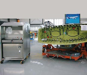

Hydraulic Test Equipment > Function Test Rig > Function Test Rig
The Function Test Rigs are designed to test the wing hydraulic systems.
They are designed to handle phosphate ester hydraulic fluids such as Hyjet
and Skydrol to Airbus specification NSA307110. They can also operate the
control servos and wing tip brakes. It is a requirement to function test
the systems and check for cleanliness standard of NAS 1638 class 7 or better
using a particle analyser. It is also required to carry out final leak checks
at the normal operating pressure of 3,000PSI and flow rate up to 3lmp/Galls per
minute. Particular care is given to ensure all aspects are proof against the
corrosive nature of Skydrol (phosphate ester).
The tests are carried out with Build Verification Test Instructions.2002 or 2002A
for A321, 2003,2011,2012 and 2013. The Function Rig has 3 channels so three
systems can be pressurised and leak checked at the same time.
For further information Click Here
The structure of the system consists of a stainless steel framework, which 
incorporates the hydraulic and electrical systems necessary for carrying out
the required function testing, and fluid sampling of the wing flaps hydraulic
pipe-work and actuators.
Fully removable access panels allow for full access to the internals of the
structure for maintenance purposes, from both sides of unit and above.
Lockable-hinged doors also allow for ready access to hydraulic power unit,
control manifolds and particle analyser for routine checks. Ventilation panels
in both top hinged doors ensure adequate airflow for cooling during normal
operation.
The mobile structure is mounted on durable castors, which allow ease of
movement,steering and locking brakes for safety.
Multiple front and rear handles mounted to the structure allow for ease
of mobility using two operators.Suitable stowage at the rear of mobile
structure is included to insure interconnecting hydraulic hoses are safely
stored and protected from contamination.
A full size, low level, integral bunded drip-tray ensures minimal external
leakage of fluid and has the capacity to hold the full reservoir volume should
the need arise.
The front of the mobile structure incorporates the main electrical control
pedestal with a sloped back panel above the electrical control pedestal for
documentation storage during testing. All equipment is designed to be
resistant to Skydrol.
The hydraulic power unit consists of a capacity reservoir, which is mounted
inside the mobile structure above the integral drip-tray. The hydraulic power
unit can be accessed via either of the lower hinged doors.
Cooler flow is supplied via a fixed screw pump close coupled to an electric 
motor via a bell-housing and coupling.The only pressure generated is that
required to push the flow through the pressure filter, air-blast cooler and back
to reservoir return.
The operations of the function rig tend to create waste energy in the form
of heat.Therefore it is necessary to remove this heat to prevent the fluid
over heating which would eventually lead to possible degradation of the fluid
and operational failure.The excess heat is removed via an air-blast cooler,
which works in conjunction with the cooling pump-motor, the dual thermostat
and pressure filter.The cooling pump will be running continuously during normal
operation filtering the fluid prior to it passing through the air-blast cooler
and back to the reservoir. When the fluid temperature reaches a predetermined
level the air blast cooler electric motor is started and cooling of the fluid
will begin.
The output manifold is used to control, function testing outputs to the wing flap
Skydrol hydraulic pipe work and actuators.The return manifold is used to control
the phosphate ester hydraulic fluids such as Skydrol and Hyjet returning from the
wing flap hydraulic pipe work during function testing.
The particle analyser is mounted in the top of the mobile structure in its own
protective stainless enclosure. It can be accessed via a top hinged door.
The unit is used to analyse the cleanliness level of the fluid returning from
the wing flap hydraulic pipe work and actuators via the return manifold. The
adjustable check valve ensures sufficient backpressure is created to ensure
skydrol fluid will pass through the analyser when sampling and can be monitored
on pressure gauge. The single point sampler is used to limit the amount of skydrol
flow passing through the analyser when operating.
The particle analyser is controlled via the electrical system where a record
and printed output of cleanliness level can be found.
The electrical system is used to fully control and monitor all aspects of the mobile
flushing rig.
Generally the electrical system consists of: -
- An electrical control pedestal mounted in the front of the mobile structure.
- A HMI touch panel mounted which aloows full control of all the mobile flushing rig functions
- A printer to give hard copy of fluid cleanliness during testing.
- All necessary hard wiring to electrical functions within the mobile flushing rig.
- Power connection point at the rear of the mobile structure.
- A warning beacon mounted on top of the mobile structure to indicate system is �live�.